|
|
 |
|
|
|
|
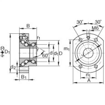
| Design of adjacent construction |
|
|
|
|
| Design of adjacent construction |
|
|
|
|
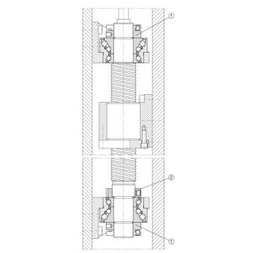
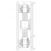
Ball screw drive with locating bearing arrangement on both sides.
The numbers in circles indicate the positions of the recommended INA locknuts (see table or under "Accessories"). |
|
| |
|
|
|
|
| |
|
|
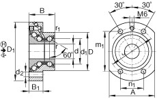
60
°
|
|
|
|
60
°
|
|
|
A
|
62
mm
|
|
|
B1
|
19
mm
|
|
|
D1
|
80
mm
|
|
|
d1
|
34,5
mm
|
|
|
d2
|
6,8
mm
|
|
|
da max
|
43
mm
|
|
|
da min
|
25
mm
|
|
|
J
|
63
mm
|
|
|
r1 min
|
0,6
mm
|
|
|
rmin
|
0,3
mm
|
|
|
| |
|
|
|
| |
Attention!
The bearings require continuous load in the main load direction H. |
|
|
m
|
0,7
kg
|
|
|
Ca
|
26000
N
|
| |
Basic dynamic load rating, axial, ← |
|
|
C0a
|
47000
N
|
| |
Basic static load rating, axial, ← |
|
|
Ca
|
44500
N
|
| |
Basic dynamic load rating, axial, in main load direction H, → |
|
|
C0a
|
110000
N
|
| |
Basic static load rating, axial, in main load direction H, → |
|
|
Cua
|
2100
N
|
| |
Fatigue limit load, axial |
|
|
nG Fett
|
5000
1/min
|
| |
Limiting speed for grease lubrication |
|
|
nϑ
|
2200
1/min
|
|
|
MRL
|
0,45
Nm
|
| |
Bearing frictional torque |
|
|
caL
|
750
N/µm
|
|
|
caL
|
1100
N/µm
|
|
|
ckL
|
260
Nm/mrad
|
|
|
Mm
|
0,553
kg * cm^2
|
| |
Mass moment of inertia for rotating inner ring |
|
|
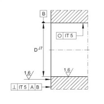
|
5
µm
|
| |
Axial runout
The axial runout data for screw drive bearing arrangements are based on the rotating inner ring. |
|
|
|
4
|
| |
Number of fixing screws to DIN 912-10.9
Screws not included in scope of delivery. |
|
|
|
M6
|
| |
Size of fixing screws to DIN 912-10.9
Tightening torque of fixing screws according to manufacturer's data.
Screws not included in scope of delivery. |
|
|
1)
|
AM20,
ZMA20/38
|
| |
Designation of recommended INA locknut |
|
|
2)
|
ZM25
|
| |
Designation of recommended INA locknut |
|
|
|
|
| |
Locknuts not included in delivery. |
|
|
|


 Molly2020-07-10 09:46:19
Welcome to my shop! Glad to serve you! Please send your question!
Molly2020-07-10 09:46:19
Welcome to my shop! Glad to serve you! Please send your question! |||
||| |||
||| |||
|||
 FAG الأخدود العميق الكرات - 61914-2RSR
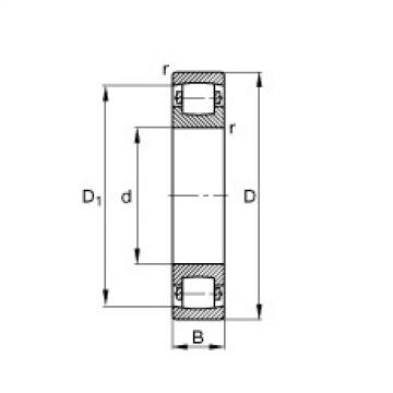 FAG برميل محامل - 20314-MB
 FAG برميل محامل - 20213-TVP
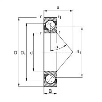 FAG الزاوي الاتصال الكرات - 71814-B-TVH
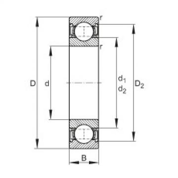 FAG الأخدود العميق الكرات - 61813-2RSR-Y